Jump to content
  • 0

Waveforms 3/Analog Discovery UART bug


krb686

Question

Using the analog discovery with waveforms 3, it seems like the UART interpreter is telling me things that are incorrect. I could be completely wrong, and maybe I don't know enough about UART framing to tell, but if that's the case let me know,

The data stream I am sending is arranged like so:

[FF pad byte] - [data(lower 6 + 2 tag bits)] - [FF pad byte] - [data(upper 6 + 2 tag bits)] - [FF pad byte] - [checksum]

To get a much better look at the bits, go to: http://s306.photobucket.com/user/Krb686/media/waveforms_uart_bug.png.html?o=0.  Then hover over the image at my photobucket, and click the zoom icon that appears in the top right.

waveforms_uart_bug.png

As you can see, those bits appear to be there, correctly, but the interpreter doesn't seem to think so.

Byte 1, the first FF, is recognized successfully.

Byte 2, the first data + tag bits, is marked as "Framing Error".  From what I understand, framing errors occur when the STOP bit does not occur at the correct time.  Clearly however, the STOP is bit is there, as the signal is HIGH where STOP is marked.

Byte 3, the second FF, is recognized successfully.

Byte 4, the second set of data + tag bits, is marked as "BREAK".  What this means, I have no clue. The line drops low after the last FF so why isn't this recognized as a new start bit? I also believe that set of bits is correct.

Byte 5, the last FF, is correct.

Byte 6, the checksum, is also marked as "BREAK", yet appears to correctly be there.


Also, this interpretation is heavily dependent on my time scale.

The above image is at 0.01ms/div (20 MHz)

At 0.02ms/div (10 MHz), the "BREAK"s go away, and are replaced with framing errors (still, seemingly incorrectly).

And you can CLEARLY see that bit #7 in the second packet is a 1, yet the interpreter tells me the value is "h0"

waveforms_uart_bug_2.png


Finally


0.05ms/div(4MHz)

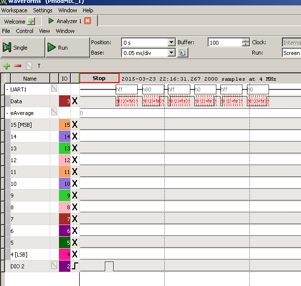
All the errors are gone, and the 2nd packet is supposedly an h80

waveforms_uart_bug_3.png


Link to comment
Share on other sites

17 answers to this question

Recommended Posts

13 hours ago, attila said:

Set Stop length to 0.5

Well, it works.

So, if I have 1 stop bit in my protocol, I have to set 0.5 in Waveforms. If 2 stop bits - 1 in Wave.. and so on.

Where is the logic? 


PS is it possible to realize autobaud?

Link to comment
Share on other sites

53 minutes ago, attila said:

Hi @Chetan

Your TX UART signal has about 111kHz rate instead the 115.2kHz standard and the interpreter does not tolerate it.
In the next software version the framing error threshold will be modified to accept such.
For now you can ignore this error, select Auto arbitrary baud or specify 111kHz Manual.

It works now. Thank you very much for the support.

Link to comment
Share on other sites

Hi @Chetan

Your TX UART signal has about 111kHz rate instead the 115.2kHz standard and the interpreter does not tolerate it.
In the next software version the framing error threshold will be modified to accept such.
For now you can ignore this error, select Auto arbitrary baud or specify 111kHz Manual.

Link to comment
Share on other sites

You can add the following script to the Logging view to adjusts the UART Rate based on minimum period. This will work correctly as long the sampling rate is at least 10 times the UART rate and the capture contains an one bit period.

var samples = Logic.Channels.UART.Data.data;

var minPulse = 999999;

var previousSample = samples[0];

var firstTransition = true;

var pulseLength = 0;


samples.forEach(function(sample){

  if(previousSample != sample){

    if(!firstTransition){

      minPulse = Math.min(minPulse, pulseLength);

    }

    firstTransition = false;

    pulseLength = 0;

  }

  pulseLength++;

  previousSample = sample

})

Logic.Channels.UART.Rate.value = Logic.Time.Rate.value / minPulse;

img11.png

Link to comment
Share on other sites

Due to clock uncertainty, the receiver or protocol interpreter needs to look for the next start after stop minus half bit period.
This is corrected for the next software release. For the current version instead 1 set 0.5, instead 2 set 1.5

Another problem with UART protocol is when the acquisition starts in the middle of a word, the start condition might be wrongly identified and misinterpreted until a valid idle or break condition is met. To solve this, the next version will have advanced digital triggering (like trigger on a specific UART word, break, pulse length, glitch, counter, I2C address...) and possibility to specify the start of protocol interpretation on the plot.

It might be helpful for you using the Stream acquisition mode (select under Run: Repeated/Shift...). With this you can capture large number of samples (1-10M) at lower rate, below 1-5MHz.

I will try to add autobaud for the version.

Thank you for the feedback.

Link to comment
Share on other sites

There is definitely a problem with the serial decoding.  Set for 9600 bps, 1 stop bit, it does not recognize the second start bit.  1 character at 9600 bps is 1.042 ms, so the second start bit does not appear to be too early.  The decoder needs to allow some variation in baud rate - (perhaps 5%) as baud rate dividers and system clocks are frequently result in a rate that is a few % out.  It could be an option to strictly enforce the baud rate.


9600.thumb.png.2912856000e35d8ecb68766c5


However, Waveforms 2 did decode it properly (similar data, same source).  


stopped.thumb.png.6a04ef2e27827feea53796


If I set stop bits to 0.5, it decodes correctly again (no picture).


Link to comment
Share on other sites

I don't understand how is the start visible in scope and not in the logic analyzer. Are you using the new version of the software from https://reference.digilentinc.com/waveforms3 ?

On the other hand, having the acquisition start in the middle of an UART character the interpretation will be wrong. It will recover, synchronize correctly when a break or character long idle is met. In the following screenshot the first char is wrong, but it is resynchronized with the second one.
This can be solved also by specifying a proper start (initial delay) in the interpreter configuration, in this case 2-3ms.

The stop length is actually a setting for the transmitter, for interper set this to a lower value or zero.

For lower sample rate, < 1-4MHz, you can use the Stream acquisition mode allowing to capture 10 M samples. The Event view in Logic Analyzer shows the list of characters.

img5.png

Link to comment
Share on other sites

A possibly related question. I'm trying to decode some UART frames with 4800bps, 8 data bits, no parity, 1 stop bit. As you can see in the attached capture, it doesn't seem to be finding the correct start bit. It's waiting for a transition from 0-1, then looking for the start bit after that. Have I set something incorrectly?

Capture.PNG

Link to comment
Share on other sites

Can you try a different framing character? One with a few transitions e.g 0xAA or ASCII Z

What baud rate are you using? Is it a little off one of the standard ones? It looks to be around 640kb/s, which is an odd rate for RS232.... by convention It is usually a multiple or factor of 115,200

PS. A break character is triggered when there is a logical 0 where a stop bit should be, and it remains that way for a long time. It is the only out of band signalling that can be done over a simple link and isn't used much.

The only use I have seen is to tell a remote server to try a different baud rate, or to interrupt the boot sequence of Cisco routers...

Hey, thanks.

Yeah I can try a different padding character, but I was under the impression FF was the best because even if the receiver is out of sync, it will still sync since it will think the FF byte is just IDLE state.

By the way, that reasoning of using an FF byte for padding opposed to an AA byte is addressed specifically in the 2nd answer by "MikeJ-UK" to a question on serial UART, on stackexchange.

The baud rate is a little weird, it's 781,250.  That's because I'm dividing down from the 100MHz clock on the Nexys 3. I have a PMOD running at 195 kHz that essentially outputs new samples every 22-ish cycles of the 195k clock I need to transmit about 85-ish bits successfully in between those samples arriving, which means I have 112 microseconds, or about 1.3 microseconds per bit. 781.25 kHz is 100Mhz / 2^7,  comes out to 1.28 us, so it's the closest I can get.

In that case then, I don't think those packets should be BREAKs, because the signal rises back to 1 before the next packet starts.

Link to comment
Share on other sites

Can you try a different framing character? One with a few transitions e.g 0xAA or ASCII Z

What baud rate are you using? Is it a little off one of the standard ones? It looks to be around 640kb/s, which is an odd rate for RS232.... by convention It is usually a multiple or factor of 115,200

PS. A break character is triggered when there is a logical 0 where a stop bit should be, and it remains that way for a long time. It is the only out of band signalling that can be done over a simple link and isn't used much.

The only use I have seen is to tell a remote server to try a different baud rate, or to interrupt the boot sequence of Cisco routers...

Link to comment
Share on other sites

Archived

This topic is now archived and is closed to further replies.

×
×
  • Create New...