Jump to content
  • 0

Understanding the captured sample with FDwfDigitalInStatusData


Lesiastas

Question

Greetings, 

Is there a way to receive 0/1 values for the captured samples using FDwfDigitalInStatusData? I tried transmitting ASCII "a" but the result for each channel is different.
I expected and wanted a result of Binary (1000 0110) using ASCII "a", but the actual result that I got was different for each DIO channels.

Actual result using DIO #0 = (1)000 0(1)(1)0
                    image.png.c38578ec8e092e0d0928bc09e010da2c.png 

Actual result using DIO #1 = (2)000 0(2)(2)0 
                     image.png.c85d4763b78d5ec9704bd889def19c43.png

Actual result using DIO #2 = (4)000 0(4)(4)0 
                 image.png.dd6526c89c776cc61bb5e472da70e34b.png

Actual result using DIO #7 = (128)000 0(128)(128)0 

                      image.png.29134ad4f86e5dbb4770b50e22e162d7.png

I want the result from DIO #1, 2, and 7 to display 0/1 values, but I haven't had any breakthroughs so far.
I'm aware that I asked this question sometime ago, but I decided to start a new thread because the other one is too long already.

The previous advice that was given to me is from this link:  

The problem is, I did  not fully understand how to apply it to the code I'm working on given below:

Dim idxDevice As Integer : idxDevice = -1
        Dim handle As Integer
        'LA Parameters
        Dim phzFreq As Double
        Dim acqMode As Integer : acqMode = 0
        Dim trigSrc As Byte : trigSrc = 3 'trigsrcDetectorDigitalIn As Byte = 3
        'Set Trigger Bits for Channels to be used
        Dim LowStateTrigger As UInteger : LowStateTrigger = 0
        Dim HighStateTrigger As UInteger : HighStateTrigger = 0
        Dim RisingEdgeTrigger As UInteger : RisingEdgeTrigger = 0
        Dim FallingEdgeTrigger As UInteger : FallingEdgeTrigger = &HFFFF
        Dim BaudRate As Double : BaudRate = 9600
        Dim nBits As Integer : nBits = 16
        Dim SampleMode As Integer : SampleMode = 0 'DwfDigitalInSampleModeSimple As Byte = 0
        '4096 for 8bit, 2048 for 16 bit, 1024 for 32bit
        Dim cSamples As Integer : cSamples = 2048
        Dim cSamplesAfterTrigger As Integer : cSamplesAfterTrigger = cSamples - 1
        Dim fReconfigure As Integer : fReconfigure = 0
        Dim fStart As Integer : fStart = 1
        Dim fReadData As Integer : fReadData = 1
        Dim sts As Byte
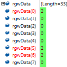
        Dim rgwData(cSamples) As UInt16
        Dim countOfDataBytes As Integer : countOfDataBytes = 2 * cSamples

        'Opening Device
        Call AD2_FDwfDeviceOpen(idxDevice, handle)

        'DigitalIn Parameters
        Call AD2_FDwfDigitalInInternalClockInfo(handle, phzFreq)
        Call AD2_FDwfDigitalInAcquisitionModeSet(handle, acqMode)
        Call AD2_FDwfDigitalInTriggerSourceSet(handle, trigSrc)
        Call AD2_FDwfDigitalInTriggerSet(handle, LowStateTrigger, HighStateTrigger, RisingEdgeTrigger, FallingEdgeTrigger)
        Call AD2_FDwfDigitalInTriggerAutoTimeoutSet(handle, 10.0)
        Call AD2_FDwfDigitalInDividerSet(handle, (phzFreq / BaudRate))
        Call AD2_FDwfDigitalInSampleFormatSet(handle, nBits)
        Call AD2_FDwfDigitalInSampleModeSet(handle, SampleMode)
        Call AD2_FDwfDigitalInBufferSizeSet(handle, cSamples)
        Call AD2_FDwfDigitalInTriggerPositionSet(handle, cSamplesAfterTrigger)

        'Configure for Reception
        Call AD2_FDwfDigitalInConfigure(handle, fReconfigure, fStart)

        'Start Reception
        Call AD2_FDwfDigitalInStatus(handle, fReadData, sts)

        'Retrieves Captured Samples
        Call AD2_FDwfDigitalInStatusData(handle, rgwData, countOfDataBytes)

        'Closing Device
        Call AD2_FDwfDigitalInReset(handle)
        Call AD2_FDwfDeviceClose(handle)

Any advice would really help a lot. Thanks in advance :lol:

Regards, 
Lesiastas

Link to comment
Share on other sites

21 answers to this question

Recommended Posts

Hi @attila

Thank you for all the help so far! Its been a huge boost overall.

I tweaked around the code you gave me and I got the results that I wanted.
I don't know how to explain it, but I changed the following declarations:
 image.png.71f6994e10330dcf3835923c999499f5.png
image.png.390b800901ece02899a47094579c1a3b.png

The results that I got are:
image.png.c795cb3538087c01ac4eae9bf30f1a00.png
Orange = represents start & stop bits.
Green = represents bit sequence of ASCII “v”.
Yellow = represents bit sequence of ASCII “U”.

The decodeUart was used and the hex value that it produced was:
(pin = 0 for DIO #0)
image.png.e29072bc4857a9929d20b748b74b1dad.png
image.png.20d2721ab9e3fdd40ce829dada03754b.png

I was wondering if I can increase cSamples to 4096 since its the Default value in the WF Logic Analyzer app because I keep getting some errors when I change cSamples.

image.png.118420fef79ad61de1adac2a93117cd5.png

Correct me if I'm wrong but, if I set The FDwfDigitalInStatusData to return an array of raw samples of 8 (Byte) bits, will it only enable DIOs #0 to 8?

Best Regards, 
Lesiastas

Link to comment
Share on other sites

Hi @attila

Thank you again for all the support you've provided me for the past weeks. I am now capable of receiving more than 409 characters using the Wrapper I created base from your example. It uses the Record acquisition mode and I set the buffer size to 3 million for now. I'll increase it when the need arises.

I used 1 UART controller and branched out its Tx pin to 2 DIO pins of the AD2 (DIO #0 & 1).
I transmitted 500 characters: 
(If Record mode is not the acquisition mode, the received result will be blank)
image.png.5781de21a05984f8ae03ccd0e928a9f3.png

For DIO # 0, it received:

image.png.743db2005e34aaad00e4bb88d2fe8bea.png

with a length of: image.png.018487e5d3f9000835c3591c39871ef3.png

For DIO #1, it received:
image.png.4c30bfa37845e036280e13fad9edaf22.png

with a length of: image.png.e5044fe832db16f99cd9a8848f7eaa30.png

I could not have done it without your guidance, thank you again and more power to you and Digilent :)

Best regards,
Lesiastas

Link to comment
Share on other sites

Hi @attila

Thank you very much for the support! Your snippet of code has been working on my end too.

Now I'm implementing the necessary APIs base from your example to be used in Record Mode for the Wrapper that I'm creating.
I'm trying to figure out what values these should return:

image.png.0435a4a5e137fc95812bbf5cc029a0d5.png

image.png.f9ffc7a15fef0f295bfc34ad5c417e56.png

Because I keep getting this error regarding the Return statement.

image.png.30e68b0616e9769ca5bcdc0ad11f9672.png

Any advice? 

Best regards,
Lesiastas

Link to comment
Share on other sites

Hi @Lesiastas

See the following code:
- Selects the 3rd device configuration for AD1/2 which allocates 16k digital buffer.
- Uses record mode with compression to capture more samples than the device buffer.

Module Module1
    Function decodeUart(ByRef rgData() As Byte, ByVal cSamplePerBit As Integer, ByVal pin As Integer) As List(Of Byte)
        Dim pData As Boolean
        Dim fData As Boolean = True
        Dim cSamples = rgData.Length
        Dim rgUart As New List(Of Byte)

        For i As Integer = 0 To cSamples - 1
            Dim s = rgData(i)
            pData = fData
            fData = 1 And (s >> pin)
            If pData <> 0 And fData = 0 Then
                Dim bValue As Integer = 0
                For b = 0 To 7
                    Dim ii = Math.Round(i + (1.499 + b) * cSamplePerBit) '''''
                    If ii >= cSamples Then
                        Exit For
                    End If
                    s = rgData(ii)
                    fData = 1 And (s >> pin)
                    If fData Then
                        bValue += (1 << b)
                    End If
                Next
                rgUart.Add(bValue)
                i += cSamplePerBit * 9.499 - 1 ''''' 1 start + 8 bits + 0.5 stop  -1 because For will increment
            End If
        Next
        Return rgUart
    End Function

    Sub Main()
        Dim hdwf As Long

        ' 3 = 4th device configuration of AD2 with 16k digital-in/out buffer
        If FDwfDeviceConfigOpen(-1, 3, hdwf) = False Then
            Dim szError As String
            FDwfGetLastErrorMsg(szError)
            System.Console.WriteLine("Device open failed" & vbCrLf & szError, vbExclamation + vbOKOnly)
            End
        End If

        ' UART channels: DIO-0 and DIO-1, h3 = (1 << 0)|(1 << 1)
        Const fsDio = &H3
        Const hzUart = 9600
        Const hzRate = hzUart * 2 '''''
        Const cSamples = 300000 ' at lest 10 * chars * 2
        Dim cBuffer As Integer

        Dim hzDI As Double
        FDwfDigitalInInternalClockInfo(hdwf, hzDI)
        FDwfDigitalInTriggerSourceSet(hdwf, trigsrcDetectorDigitalIn)
        ' falling edge of any specified channel
        FDwfDigitalInTriggerSet(hdwf, 0, 0, 0, fsDio)
        FDwfDigitalInDividerSet(hdwf, hzDI / hzRate)
        FDwfDigitalInSampleFormatSet(hdwf, 8)
        FDwfDigitalInBufferSizeInfo(hdwf, cBuffer)

        If cSamples > cBuffer Then '
            FDwfDigitalInAcquisitionModeSet(hdwf, acqmodeRecord)
            FDwfDigitalInTriggerPrefillSet(hdwf, 0)
            ' number of samples after trigger
            FDwfDigitalInTriggerPositionSet(hdwf, cSamples)
            ' we are interested only on toggles of the specified channels
            FDwfDigitalInSampleSensibleSet(hdwf, fsDio)
        Else
            FDwfDigitalInBufferSizeSet(hdwf, cSamples)
            FDwfDigitalInTriggerPositionSet(hdwf, cSamples - 10)
        End If

        FDwfDigitalInConfigure(hdwf, 1, 1)

        FDwfDigitalInDividerGet(hdwf, hzRate) ' get the actual rate
        Const cSamplePerBit = hzRate / hzUart
        Dim rgData(cSamples) As Byte
        Dim sts As Byte
        Dim fOverflow As Boolean = False
        Dim iSample As Integer = 0

        If cSamples > cBuffer Then ' record
            Dim cAvailable As Integer
            Dim cLost As Integer
            Dim cCorrupted As Integer
            While iSample < cSamples
                If FDwfDigitalInStatus(hdwf, 1, sts) = 0 Then
                    Return
                End If
                If sts = DwfStateDone Or sts = DwfStateTriggered Then
                    FDwfDigitalInStatusRecord(hdwf, cAvailable, cLost, cCorrupted)
                    If cLost <> 0 Or cCorrupted <> 0 Then
                        fOverflow = True
                    End If
                    cAvailable = Math.Min(cAvailable, cSamples - iSample)
                    Dim rgTemp(cAvailable) As Byte
                    ' in other porgramming languages use pass pointer to rgData[iSample]
                    FDwfDigitalInStatusData(hdwf, rgTemp, 1 * cAvailable)
                    For i = 0 To cAvailable - 1
                        rgData(iSample) = rgTemp(i)
                        iSample += 1
                    Next
                End If
                If sts = DwfStateDone Then
                    Exit While
                End If
            End While
        Else
            While True
                If FDwfDigitalInStatus(hdwf, 1, sts) = 0 Then
                    Return
                End If
                If sts = DwfStateDone Then
                    Exit While
                End If
            End While
            iSample = rgData.Length
            FDwfDigitalInStatusData(hdwf, rgData, 1 * rgData.Length)
        End If

        FDwfDeviceCloseAll()

        Dim rg0 = decodeUart(rgData, cSamplePerBit, 0) ' DIO 0
        'Dim rg1 = decodeUart(rgData, cSamplePerBit, 1) ' DIO 1

        'System.Console.Write("Hex  0: ")
        'For i = 0 To rg0.Count - 1
        '    System.Console.Write(" 0x" + Conversion.Hex(rg0(i)))
        'Next
        'System.Console.WriteLine()

        System.Console.WriteLine("Text 0: " & System.Text.Encoding.ASCII.GetString(rg0.ToArray))

        System.Console.WriteLine("Samples: " & iSample & "  Chars: " & rg0.Count)
        If fOverflow Then
            System.Console.WriteLine("Buffer overflow!")
        End If

    End Sub

End Module

image.png.5568b0c2f3fdc5e90c28d6a76db24f84.png

Link to comment
Share on other sites

Hi @attila

I observed that the maximum size received by the FDwfDigitalInStatusData is 409 characters. 

I transmitted 420 characters:
(I counted the "0" to confirm its 420 characters)

image.png.dc14374ddb4d423418854392785e837b.png

What I received was this:
image.png.ce53d312bf8561734bfdcbfc41e56902.png

Its length is only 409, a few characters were missing.

I also tried changing cSamples to a higher value:

image.png.1cb9bc497ef1592ecaef9fca67df5a2c.png

The result is:

image.png.b9414ec931fd6a8e8f11ce4b60719fcc.png

All bits returned were high bits and no ASCII values were decoded.

Here's my question:

If I want to receive a minimum of 8000 characters, which is better to use: the Record Mode or the Repeated Mode of the WF Logic Analyzer app?
If you'll recommend Record Mode, can you please provide an example on how to use FDwfDigitalInStatusRecord?
Because the example available in the samples folder is quite confusing.

Best regards, 
Lesiastas

Link to comment
Share on other sites

Hi @attila

Thanks for all the help! I managed to replace all unsupported operators in VBA to make it work as expected.
I'm now able to receive the raw samples from FDwfDigitalInStatusData and parse it to return ASCII values.

I transmitted ASCII "vu":
image.png.28827e526a3c0b4f1dc80a192c380e83.png

And the result in VBA is this:
(DIO #0 & #1 were used for reception)
image.png.edde84ac7cd38e95aef5f8ed65891eb1.png

Orange = represents start & stop bits.
Yellow = represents bit sequence of ASCII “v”.
Green = represents bit sequence of ASCII “U”.
image.png.11b22737bacfe8063a13841270f4f5d3.png

Other examples that I used are also successful:
image.png.21c75269cd263ab7c892787f5b62ec8c.png
image.png.5cc656eb4530afbbcea90dea81315d6d.png

image.png.a030ecc63273e43933dd117028b21336.png
image.png.99107eb139427ef176a05edca3834148.png

I also tried other values for the variable pin and I got the results that I wanted as well.

Thanks again for all the help and support. More power to you and Digilent :) 

Best regards,
Lesiastas


Link to comment
Share on other sites

Hi @attila

I've gotten the results that I wanted!
Thanks for all the help regarding the UART Decoder Algorithm! 

Examples of the received and parsed messages that I used are:
image.png.aa61596148cfdc6bbe0c1525d48a563b.png
image.png.359ee2d2e3d9dd4dceb1f8f571f8dc2a.png

image.png.638e448a5debffbdc7c222cc73ca03c0.png
image.png.b96b6bad615a6d8e504908154aa4cf59.png

I also increased the buffer size to 4095 to accommodate for messages with bigger size.
image.png.4ee2e74dc018b6e9c627da0e7bcdcbff.png

Result is:
image.png.22b18685b0aae4ba2553c5a6f365f37a.png
image.png.5db0f2d22b74ebdcb7cb7c2fea75d568.png

The next step for me is to reference the working VB Logic Analyzer Wrapper to a VBA Macro Script Project. 
Errors occurred and I observed that the UART Decoder Algorithm uses some operators not supported by VBA.

image.png.015655365de9fbd80d32ce3ad6634b05.png

Can you please help me understand what should I do to fix this error?

Best Regards,
Lesiastas

Link to comment
Share on other sites

Hi @Lesiastas

The rg0 will get its value after you step over the respective line, after the decode function is executed.

Byte sampling:

image.png.a88a358a7425cce8d9163c2ea78b537e.png

image.png.df8aa6957208ca3641487847d4a8a748.png

Module Module1
    Function decodeUart(ByRef rgData() As Byte, ByVal cSamplePerBit As Integer, ByVal pin As Integer) As List(Of Byte)
        Dim pData As Boolean
        Dim fData As Boolean = False
        Dim cSamples = rgData.Length
        Dim rgUart As New List(Of Byte)

        For i As Integer = 0 To cSamples - 1
            Dim s = rgData(i)
            pData = fData
            fData = 1 And (s >> pin)
            If pData <> 0 And fData = 0 Then
                Dim bValue As Integer = 0
                For b = 0 To 7
                    Dim ii = Math.Round(i + (1.499 + b) * cSamplePerBit) '''''
                    If ii >= cSamples Then
                        Exit For
                    End If
                    s = rgData(ii)
                    fData = 1 And (s >> pin)
                    If fData Then
                        bValue += (1 << b)
                    End If
                Next
                rgUart.Add(bValue)
                i += cSamplePerBit * 9.499 - 1 ''''' 1 start + 8 bits + 0.5 stop  -1 because For will increment
            End If
        Next
        Return rgUart
    End Function

    Sub Main()
        Dim hdwf As Long

        If FDwfDeviceOpen(-1, hdwf) = False Then
            Dim szError As String
            FDwfGetLastErrorMsg(szError)
            System.Console.WriteLine("Device open failed" & vbCrLf & szError, vbExclamation + vbOKOnly)
            End
        End If

        Const hzUart = 9600
        Const hzRate = hzUart * 1 '''''
        Const cSamples = 1000

        Dim hzDI As Double
        FDwfDigitalInInternalClockInfo(hdwf, hzDI)
        FDwfDigitalInTriggerSourceSet(hdwf, trigsrcDetectorDigitalIn)
        FDwfDigitalInTriggerSet(hdwf, 0, 0, 0, &HFFFF) 'any falling edge
        'FDwfDigitalInTriggerAutoTimeoutSet(hdwf, 10.0)
        FDwfDigitalInDividerSet(hdwf, hzDI / hzRate)
        FDwfDigitalInSampleFormatSet(hdwf, 8)
        FDwfDigitalInBufferSizeSet(hdwf, cSamples)
        FDwfDigitalInTriggerPositionSet(hdwf, cSamples - 10)

        FDwfDigitalInConfigure(hdwf, 1, 1)

        Dim sts As Byte
        While True
            If FDwfDigitalInStatus(hdwf, 1, sts) = 0 Then
                Return
            End If
            If sts = DwfStateDone Then
                Exit While
            End If
        End While

        FDwfDigitalInDividerGet(hdwf, hzRate) ' get the actual rate
        Const cSamplePerBit = hzRate / hzUart

        Dim rgData(cSamples) As Byte
        FDwfDigitalInStatusData(hdwf, rgData, 1 * rgData.Length)

        Call FDwfDeviceCloseAll()

        Dim rg0 = decodeUart(rgData, cSamplePerBit, 0)

        System.Console.Write("Hex  0: ")
        For i = 0 To rg0.Count - 1
            System.Console.Write(" 0x" + Conversion.Hex(rg0(i)))
        Next
        System.Console.WriteLine()
        System.Console.WriteLine("Text 0: " + System.Text.Encoding.ASCII.GetString(rg0.ToArray))

    End Sub
End Module


Link to comment
Share on other sites

Hi @attila

Thanks for the clarification and sorry for the confusion.

What I meant by 'enable DIOs' is this: Does changing the FDwfDigitalInSampleFormatSet affect how many DIO pins can be used in receiving data?
 For example, if I set the FDwfDigitalInSampleFormatSet to 8 (Byte) bits, will I only be receiving data from DIOs 0 to 7 of Analog Discovery 2? 

I also did the changes you advised for 8 (Byte) bit data. 

......
Function decodeUart(ByRef rgData() As Byte,...
......
FDwfDigitalInSampleFormatSet(hdwf, 8)
......
Dim rgData(cSamples) As Byte
FDwfDigitalInStatusData(hdwf, rgData, rgData.Length)
'FDwfDigitalInStatusDataUShort uses rgData as UShort

Transmitted data was ASCII "vU" and the bit sequence was captured:
(DIO #0 & 1 was used that's why 3 bits was received)

image.png.b9c12014f768b90180ba683f22a799c4.png

But when I step at the rg0 line, the result that I get is blank:

image.png.7416021b5fe9b2344bf9c904e23ef2e5.png

image.png.8de695b57e37b976cbf9810c6625e576.png

Any advice regarding this error?

Best Regards,
Lesiastas

Link to comment
Share on other sites

Hi @Lesiastas

Added to the previous post the following to prevent such exception:

If ii >= cSamples Then
    Exit For
End If

I'm not sure what you mean by 'enable DIOs'... The Digital-In functions are not enabling any kind of output on DIOs. Internally for AD2 the digital-in always samples at 16bits, just the FDwfDigitalInStatusData format changes: 8, 16 or 32 bits.
If you want you can use 8 bit data you can do with the following changes:

...
Function decodeUart(ByRef rgData() As Byte, ....
...
FDwfDigitalInSampleFormatSet(hdwf, 8)
...
Dim rgData(cSamples) As Byte
FDwfDigitalInStatusDataUShort(hdwf, rgData, rgData.Length)
...


Link to comment
Share on other sites

Hi @Lesiastas

You should use higher sample rate to capture raw data than the UART rate.
Otherwise due to clock jitter and signal slew rate the capture could be wrong. Imagine on sample could be captured exactly on bit start and next bit on the end of the same bit, instead of next bit start...

Anyway, here I have modified the decodeUart to work with sample rate = uart rate, see the lines marked with ' ' ' '

Module Module1
    Function decodeUart(ByRef rgData() As UShort, ByVal cSamplePerBit As Integer, ByVal pin As Integer) As List(Of Byte)
        Dim pData As Boolean
        Dim fData As Boolean = False
        Dim cSamples = rgData.Length
        Dim rgUart As New List(Of Byte)

        For i As Integer = 0 To cSamples - 1
            Dim s = rgData(i)
            pData = fData
            fData = 1 And (s >> pin)
            If pData <> 0 And fData = 0 Then
                Dim bValue As Integer = 0
                For b = 0 To 7
                    Dim ii = Math.Round(i + (1.499 + b) * cSamplePerBit) '''''
                    If ii >= cSamples Then
                        Exit For
                    End If
                    s = rgData(ii)
                    fData = 1 And (s >> pin)
                    If fData Then
                        bValue += (1 << b)
                    End If
                Next
                rgUart.Add(bValue)
                i += cSamplePerBit * 9.499 - 1 ''''' 1 start + 8 bits + 0.5 stop  -1 because For will increment
            End If
        Next
        Return rgUart
    End Function

    Sub Main()
        Dim hdwf As Long

        If FDwfDeviceOpen(-1, hdwf) = False Then
            Dim szError As String
            FDwfGetLastErrorMsg(szError)
            System.Console.WriteLine("Device open failed" & vbCrLf & szError, vbExclamation + vbOKOnly)
            End
        End If

        Const hzUart = 9600
        Const hzRate = hzUart * 3 '''''
        Const cSamples = 1000

        Dim hzDI As Double
        FDwfDigitalInInternalClockInfo(hdwf, hzDI)
        FDwfDigitalInTriggerSourceSet(hdwf, trigsrcDetectorDigitalIn)
        FDwfDigitalInTriggerSet(hdwf, 0, 0, 0, &HFFFF) 'any falling edge
        'FDwfDigitalInTriggerAutoTimeoutSet(hdwf, 10.0)
        FDwfDigitalInDividerSet(hdwf, hzDI / hzRate)
        FDwfDigitalInSampleFormatSet(hdwf, 16)
        FDwfDigitalInBufferSizeSet(hdwf, cSamples)
        FDwfDigitalInTriggerPositionSet(hdwf, cSamples - 10)

        FDwfDigitalInConfigure(hdwf, 1, 1)

        Dim sts As Byte
        While True
            If FDwfDigitalInStatus(hdwf, 1, sts) = 0 Then
                Return
            End If
            If sts = DwfStateDone Then
                Exit While
            End If
        End While

        FDwfDigitalInDividerGet(hdwf, hzRate) ' get the actual rate
        Const cSamplePerBit = hzRate / hzUart

        Dim rgData(cSamples) As UInt16
        FDwfDigitalInStatusDataUShort(hdwf, rgData, 2 * rgData.Length)

        Call FDwfDeviceCloseAll()

        Dim rg0 = decodeUart(rgData, cSamplePerBit, 0)

        System.Console.Write("Hex  0: ")
        For i = 0 To rg0.Count - 1
            System.Console.Write(" 0x" + Conversion.Hex(rg0(i)))
        Next
        System.Console.WriteLine()
        System.Console.WriteLine("Text 0: " + System.Text.Encoding.ASCII.GetString(rg0.ToArray))

    End Sub

End Module


Link to comment
Share on other sites

Hi @attila

Your advice really helped and I now understand the setting that needs to be used for each Logic Analyzer API.
I'm trying to implement the decodeUart to our own version of here: UART_for_Reception.rar

ASCII characters "vU" were transmitted to test the code.
The expected result was:
Hex: 0x76 and  0x55
UART:  "vU"

The actual result that was being received are:

image.png.40454485d68656578bb4b56fc083b38b.png

Orange = represents start & stop bits.
Green = represents bit sequence of ASCII “v”.
Yellow = represents bit sequence of ASCII “U”.

The decodeUart was used but the hex value that it produced was:
(pin = 0 for DIO #0)

image.png.a467c2f1d76705e0daa98e891709a1f2.png

image.png.03b2c6df7578334f6dd05c45cec962fa.png

I don't understand why this happens. Can you please check the code provided above?
Thanks in advance!

Best Regards,
Lesiastas

Link to comment
Share on other sites

Hi @Lesiastas

The Logic Analyzer interface captures raw time domain samples and decodes the protocol in software, like it is in the above example.
The Protocol tool is similar to the FdwfDigitalUart/Spi/I2c operation. The encoding/decoding takes place in the device, storing only the relevant samples for the protocol, like on SPI clock rising or falling edge, or detects UART starts and stores the required ~9 samples-bits.

In the above example you can decode multiple UART lines from the same captured data, like:
Dim rg0 = decodeUart(rgData, cSamplePerBit, 0) 'DIO-0
Dim rg1 = decodeUart(rgData, cSamplePerBit, 1) 'DIO-1
Dim rg2 = decodeUart(rgData, cSamplePerBit, 2) 'DIO-2
...

The cSamplePerBit should be Double.

Link to comment
Share on other sites

Hi @attila

Thanks for the snippet of code! I appreciate it  and it made me understand a lot of things.

I was just wondering:

1. Is the UART API in the WF Protocol app different from the UART mentioned in the WF Logic Analyzer app? 

image.png.39a6bb3ad38cf8c952e336735f68f1fd.png

Because the Add UART setting looks very familiar with the WF Protocol app's settings.

Correct me if I'm wrong, but looking at the DecodeUART script, I think the values set there are used in the DecodeUART script to enable different DIOs right?

Thanks again for all the support!

Regards, 
Lesiastas

Link to comment
Share on other sites

Hi @Lesiastas

For the VB and C# wrappers I have added digital-in-data function variants with byte, short, integer data types. See SDK/ samples/ vb/ dwf.vb
https://forum.digilentinc.com/topic/8908-waveforms-beta-download/

Here you have a VB UART decoder example: vb.zip
To decode from other lines add, like: decodeUart(rgData, cSamplePerBit, 2) 'DIO-2

Module Module1
    Function decodeUart(ByRef rgData() As UShort, ByVal cSamplePerBit As [-Integer-] Double, ByVal pin As Integer) As List(Of Byte)
        Dim pData As Boolean
        Dim fData As Boolean = False
        Dim cSamples = rgData.Length
        Dim rgUart As New List(Of Byte)

        For i As Integer = 0 To cSamples - 1
            Dim s = rgData(i)
            pData = fData
            fData = 1 And (s >> pin)
            If pData <> 0 And fData = 0 Then
                Dim bValue As Integer = 0
                For b = 0 To 7
                    Dim ii = Math.Round(i + (1.5 + b) * cSamplePerBit)
                    s = rgData(ii)
                    fData = 1 And (s >> pin)
                    If fData Then
                        bValue += (1 << b)
                    End If
                Next
                rgUart.Add(bValue)
                i += cSamplePerBit * 9.5 ' 1 start + 8 bits + 0.5 stop
            End If
        Next
        Return rgUart
    End Function

    Sub Main()
        Dim hdwf As Long

        If FDwfDeviceOpen(-1, hdwf) = False Then
            Dim szError As String
            FDwfGetLastErrorMsg(szError)
            System.Console.WriteLine("Device open failed" & vbCrLf & szError, vbExclamation + vbOKOnly)
            End
        End If

        Const hzUart = 9600
        Const hzRate = hzUart * 10
        Const cSamples = 1000

        Dim hzDI As Double
        FDwfDigitalInInternalClockInfo(hdwf, hzDI)
        FDwfDigitalInTriggerSourceSet(hdwf, trigsrcDetectorDigitalIn)
        FDwfDigitalInTriggerSet(hdwf, 0, 0, 0, &HFFFF) 'any falling edge
        'FDwfDigitalInTriggerAutoTimeoutSet(hdwf, 10.0)
        FDwfDigitalInDividerSet(hdwf, hzDI / hzRate)
        FDwfDigitalInSampleFormatSet(hdwf, 16)
        FDwfDigitalInBufferSizeSet(hdwf, cSamples)
        FDwfDigitalInTriggerPositionSet(hdwf, cSamples - 10)

        FDwfDigitalInConfigure(hdwf, 1, 1)

        Dim sts As Byte
        While True
            If FDwfDigitalInStatus(hdwf, 1, sts) = 0 Then
                Return
            End If
            If sts = DwfStateDone Then
                Exit While
            End If
        End While

        FDwfDigitalInDividerGet(hdwf, hzRate) ' get the actual rate
        Const cSamplePerBit = hzRate / hzUart

        Dim rgData(cSamples) As UInt16
        FDwfDigitalInStatusDataUShort(hdwf, rgData, 2 * rgData.Length)

        Call FDwfDeviceCloseAll()

        Dim rg0 = decodeUart(rgData, cSamplePerBit, 0)

        System.Console.Write("Hex  0: ")
        For i = 0 To rg0.Count - 1
            System.Console.Write(" 0x" + Conversion.Hex(rg0(i)))
        Next
        System.Console.WriteLine()
        System.Console.WriteLine("Text  0:" + System.Text.Encoding.ASCII.GetString(rg0.ToArray))

    End Sub

End Module

image.png.8bf0851f2e397828b9a01d28f6d0313b.png

Link to comment
Share on other sites

Hi @attila

Thanks for clearing things about the Custom Logic Analyzer Script example. I'm beginning to understand what I need to do now.

Just to make things clear:

On 9/2/2019 at 6:54 PM, attila said:

2. The SampleMode should be 8, 18 or 32

1. I think the SampleMode should be 8, 16, or 32. Correct me if I'm wrong, but this is applied to the  FDwfDigitalInSampleFormatSet right?

2. Base from my understanding, if I tweak the FDwfDigitalInStatusData to return an  array of raw samples of 16 (UShort) bits, it will enable DIOs 0 to 15. What changes can I make to the dwf declaration given below so that it can be compatible with the UShort format?

Quote

<DllImport("dwf.dll", EntryPoint:="FDwfDigitalInStatusData", CallingConvention:=CallingConvention.Cdecl)>
    Function FDwfDigitalInStatusData(ByVal hdwf As Integer, <MarshalAs(UnmanagedType.LPArray)> rgData() As Byte, ByVal countOfDataBytes As Integer) As Integer
    End Function

3. I don't think I'll be using the 32 (UInteger) bits format because the device I'm using is Analog Discovery 2, which only have DIOs 0 to 15.

4. Base from my understanding, I can use the java script example in the Logic Analyzer Custom to decode the raw samples from FDwfDigitalInStatusData right? The language that I'm mostly using right now is in VB6 and I don't really understand java script. Can you please provide a VB6 script version of that Logic Analyzer Custom Script? Thanks in advance!

Regards, 
Lesiastas

Link to comment
Share on other sites

Hi @attila

A follow up question: How is it that the UART setting in the Protocol GUI can only handle 1 Rx at a time, but the UART setting in the Logic Analyzer can be used for multiple channels? 

image.png.dfe7722116ee2f0ff59389d1bbb58079.png

Can you please help me in understanding the above setting? Can I do the same with the code that I'm working on?

Regards,
Lesiastas

Link to comment
Share on other sites

Hi @attila
Thanks for answering the several settings of the code I'm working on. I'll apply just that and see the results that I'm getting.

I transmitted the ASCII characters "Dog" to the Logic Analyzer. As I observed in the WaveForms Logic Analyzer GUI, the bit sequence was displayed and it was decoded into its ASCII equivalent because of the UART setting. This is what I want to replicate but I'm having a hard time understanding how it works. 

image.png.35707d13a91cb54ae43239930ec0adde.png

Sorry but I'm having a hard time in finding out how I can pass the FDwfDigitalInStatusData raw samples of 16 (UShort) to the FDwfDigitalUartRx. Do you have a sample code where the FDwfDigitalInStatusData data is passed to the FDwfDigitalUartRx for it to be decoded into ASCII format like what is done in the Logic Analyzer GUI?

Thanks in advance!

Regards,
Lesiastas

Link to comment
Share on other sites

Hi @Lesiastas

1. With the "FallingEdgeTrigger = &HFFFF" you are triggering on falling edge on any DIO 0:15
2. The SampleMode should be 8, 18 or 32 
3. The FDwfDigitalInStatusData returns array of raw samples of 8 (Byte), 16 (UShort), 32 (UInteger) bits; DIO 0:8, 0:15, 0:31
This data needs to be decoded to UART.
You could also use the FDwfDigitalUart functions to send/receive encoded/decoded UART data.


Link to comment
Share on other sites

Archived

This topic is now archived and is closed to further replies.

×
×
  • Create New...