


epsilon
-
Posts
15 -
Joined
-
Last visited
Content Type
Profiles
Forums
Events
Gallery
Posts posted by epsilon
-
-
-
Quote
// for feedback -1 q3.0 +1 q3.0
assign y = (v > 0) ? 3'b111 : 3'b001;
I think there might be a small error here. y should track v[2], the DAC's output, i.e. if v[2]==1 y should be 1, if v[2]==0 y should be -1. In the code above, if v==0, v[2] == 0, but y will be 1. Testing against v[2]==0 or (v>=0) would be more accurate.
I tested with a square wave. I recorded the bitstream, sent it through a low-pass filter, and plotted the magnitude spectrum. In the 'fixed' version (sqr_fft_after), the noise floor is cleaner than before (sqr_fft_before).
I'm not a signal-processing expert by any means. I was just wondering why the output of the 2nd order DAC above was noisier than that of another implementation I tested against (https://github.com/briansune/Delta-Sigma-DAC-Verilog), and it turned out to be the (v>0) test.
Best regards,
Ruben.


-
I added an SD-Card Controller and File System to BoxLambda:
https://epsilon537.github.io/boxlambda/sd-and-fs-bring-up/
-
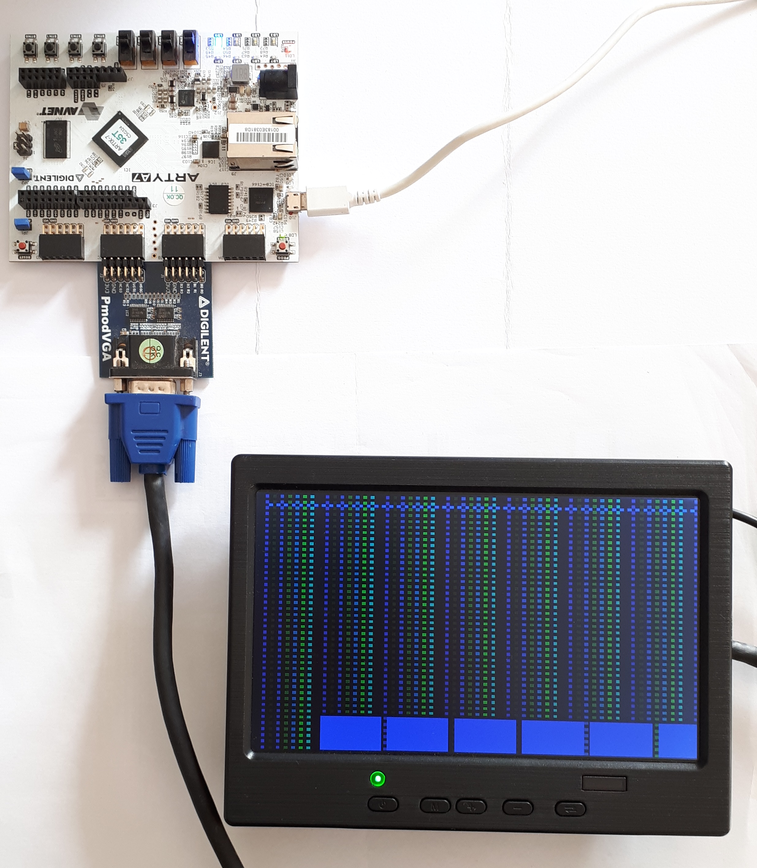
I integrated the VERA (Versatile Embedded Retro Adapter) core into BoxLambda: https://epsilon537.github.io/boxlambda/integrating-vera/
-
Hi all,
I integrated the LiteX SDRAM Memory Controller into BoxLambda. Here's the write-up: https://epsilon537.github.io/boxlambda/exit-mig-enter-litedram/
Cheers,
Epsilon.
-
I just published a follow-up to my Hello Debugger post about OpenOCD JTAG Debug bring-up for my Ibex RISCV-based project.
https://epsilon537.github.io/boxlambda/openocd-loose-ends/
I included some notes about accessing the Arty A7 from Vivado running on WSL. If I recall correctly, there were some questions about that on this forum.
Cheers,
Epsilon.
-
Hi all,
All while ago, I started BoxLambda, a Blog and open-source project with the goal of creating a retro-style FPGA-based microcomputer. The microcomputer serves as a platform for software and RTL experimentation.
https://epsilon537.github.io/boxlambda/
https://github.com/epsilon537/boxlambda/tree/develop
Does the world need another retro-style computer? Probably not, but I do. I’m a software engineer and I’ve been studying FPGA development for more than a year now, specifically for this project.
BoxLambda is a system-integration project. There's very little from-scratch RTL development. The project is mostly about studying relevant GitHub projects (CPU, graphics, sound cores etc.) and bringing them into the BoxLambda SoC.
Since the project is based on Digilent's Arty and Nexys A7, I thought some of the folks on this forum might find it interesting.
Recently, I've been working on setting up OpenOCD JTAG Debug access for BoxLambda:
https://epsilon537.github.io/boxlambda/hello-debugger/
Let me know what you think.
Cheers,
Epsilon.
-
I got this level shifter: https://joy-it.net/en/products/COM-KY051VT
I'm happy to report that all four of my PS/2 peripherals are working fine when using this level shifter (without it, I only have one keyboard that works).
The PS/2 PMOD would have been a better PMOD if such a level shifter was part of the PMOD, IMO.
Cheers,
Ruben.
-
Thank you JColvin,
In the meantime I was able to score another PS/2 keyboard at a garage sale and this one is working fine at 3.3V. I also got a PS/2 mouse, which sadly does not work at 3.3V, but I confirmed it does work at 5V (on a breadboard with a 5V supply and a scope to monitor the signals).
I initially thought that this PMOD could be a solution: https://digilent.com/shop/pmod-lvlshft-logic-level-shifter/
Looking at bit more closely however, it doesn't look like this PMOD will work with one wire interfaces. You have to choose a direction with the jumpers. I guess I'll have to put a bidirectional level shifter on a breadboard and take it from there. That, or I keep buying PS/2 mice at garage sales until I find one that works at 3.3V :-)
Cheers,
Ruben.
-
Hi,
I have an Arty A7, a PS/2 PMOD and an old PS/2 keyboard. At 3.3V this keyboard doesn't show any sign of life. I suspect it actually needs 5V.
I see there's a jumper on the PMOD that allows you to hook up an external 5V supply. Looking at the schematic however, I don't see how this can work. There's no level shifter on the PMOD. The data and clock lines would get pulled up to 5V and damage the FPGA.
Am I supposed to hook up the PS/2 PMOD to a level shifter PMOD if I want to use it at 5V?
Btw, isn't PS/2 Vcc supposed to be 5V? Is the idea of this PS/2 PMOD to hook up a PS/2 peripheral, which is supposed to run at 5V, to 3V3 instead and hope for the best?Thanks for any help,
Ruben.
-
Bummer. In that case, as already suggested by another user in this forum, would you consider releasing the PIC24 code you used on the NEXYS 3/4 boards to do the USB>PS/2 conversion?
Thanks,
Ruben.
-
Hi,
It's been a while, but if we keep asking maybe some day it'll actually happen ?: Any progress on a USB HID PMOD board?
Cheers,
Ruben.
-
Thank you Arthur. I am currently using blocking assignments (see my naive testbench code below). As a beginner I have yet to learn about the the subtleties of non-blocking vs. blocking assignment in the context of a testbench, but if the upshot is that it makes the level rising edge fall at a more convenient time relative to the state transition, wouldn't I be masking an issue instead of finding one with my testbench?
Or am I looking at this wrong and will there in practice always be a noticeable pulse due to propagation delay through the state register?
module dual_edge_detect_sim();
localparam T=10;
logic clk, reset;
logic level;
logic tick;
edge_detect_mealy uut(.*);
//clk
always begin
clk = 1'b1;
#(T/2);
clk = 1'b0;
#(T/2);
end
//reset
initial
begin
reset = 1'b1;
level = 1'b0;
#(T);
reset = 1'b0;
#(2*T);
level = 1'b1;
#(5*T);
level = 1'b0;
#(5*T);
level = 1'b1;
@(posedge clk);
#(T/4);
level = 1'b0;
@(negedge clk);
#(5*T);
level = 1'b1;
#(5*T);
level = 1'b0;
#(5*T);
level = 1'b1;
@(posedge clk);
#(T/4);
level = 1'b0;
@(negedge clk);
#(5.5*T);
$stop;
end
endmodule -
Hi all,
I'm working my way through 'FPGA Prototyping by SystemVerilog examples' book from P. P. Chu.
I'm a bit confused about the Mealy machine based edge detector in section 5.3.1. I'll copy the source code below.
It looks like if a rising edge occurs immediately before the rising edge of the clock, the resulting 'tick' pulse can be super short. So short in fact, that it doesn't even show up in simulation (see first two pulses in attached waveform). Isn't this a recipe for missing rising edges?
This book comes highly recommended as a resource for learning FPGA programming, so it's probably me making a mistake here, not the book, but I don't see it.
Thanks for any insight.
Ruben.
module edge_detect_mealy
(
input logic clk, reset,
input logic level,
output logic tick
);// fsm state type
typedef enum {zero, one} state_type;// signal declaration
state_type state_reg, state_next;// state register
always_ff @(posedge clk, posedge reset)
if (reset)
state_reg <= zero;
else
state_reg <= state_next;// next-state logic and output logic
always_comb
begin
state_next = state_reg; // default state: the same
tick = 1'b0; // default output: 0
case (state_reg)
zero:
if (level)
begin
tick = 1'b1;
state_next = one;
end
one:
if (~level)
state_next = zero;
default: state_next = zero;
endcase
end
endmodule


BoxLambda, a Arty/Nexys A7-based retro-style microcomputer
in Project Vault
Posted
Two Devlog updates:
An attempt at a PicoRV32-based Soft DMA Controller - Optimizations:
https://epsilon537.github.io/boxlambda/picorv32-dma-controller-pt2/
The Interconnect, Harvard Architecture, and Dual Port RAM:
https://epsilon537.github.io/boxlambda/interconnect/